
Other KMotionCNC Screens:
(Click on Image to Jump to related help)
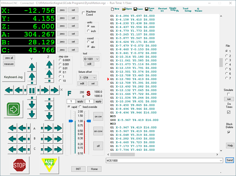
KMotionCNC allows the user to edit, execute, and view G Code Programs. GCode is a historical language for defining Linear/Circular/Helical Interpolated Motions often used to program numerically controlled machines (CNC Machines).
KMotion has various screen “faces”. The one shown above is for “Basic 6 axes”. Others may be selected on the Tool Setup Screen.
Right-mouse-clicking the title bar in KMotionCNC brings up a context menu for access to the Tool Setup Screens as well as the version (under “About KMotionCNC”).

See the Quick Reference at left for commonly used G Code commands.
Display

The 4 axis Display along the top of the screen indicated the current position of each axis. The units of the display are in either mm or inches depending on the current mode of the interpreter (see Coordinate System Units).
The displayed position will match the g -code programmed position (i.e. last G1 commanded position) which is not necessarily the actual machine tool position if global or fixture offsets are in use.
The color of the display gives an indication of current status.
Green – indicates normal status, hardware is connected, axis is enabled, and the displayed position is the current commanded tool position in GCode coordinates.
Orange – indicates normal status, hardware is connected, axis is enabled, and the displayed position is the current tool position in Raw Machine Coordinates (G53 without any Global Offset (G92) or Fixture Offset (G54+).
White – indicates simulation mode is selected. The displayed position is the current position after the last line of interpreted G code.
Yellow – indicates hardware disconnected or axis disabled. The displayed position is invalid
Cyan – indicates normal status, hardware is connected, axis is enabled, and the displayed position is the current measured tool position in GCode coordinates. Available when Encoders or other feedback device is used and the Encoder mode is selected on the Tool Setup | Trajectory Planner Screen.
Zero/Set Origin
 Allows zeroing or setting the respective axis. This is accomplished by adjusting the Global Offsets (G52/G92) or by adjusting the currently selected Fixture Offset. Which is offset is adjusted is determined by the Tool Setup Parameter described here. The original Raw Machine Coordinates will remain unchanged, so the effect of these operations will only be apparent if displaying Machine Coordinates is de-selected, see below. For further information see system offsets.
Coordinate System Origin
 When checked, the displayed position is the current tool position in Raw Machine Coordinates (G53 without any Global offset (G92) or Fixture Offset (G54+). Machine coodinates are relative to the fixed machine home position.
Unchecked displays the normal GCode Coordinate relative to the “floating” origin which may be moved by changing either the global offset (G92) and/or a Fixture Offset.
Coordinate System Units / Mode
 Displays the current mode of the G code interpreter.
G20 selects English Inch units
G21 selects Metric mm units
G90 selects Absolute Coordinates
G91 selects Relative Coordinates
Fixture Offset

Displays and allows changing of the current Fixture Offset. KMotionCNC supports 9 Fixture offsets. Each Fixture may be programmed to introduce an arbitrary x,y,z,a offset. Use the G10L2Pn command to set the offset associated with the fixture #n. An example might be:
G10 L2 P3 X10.0 Y20.0 Z30.0 which sets Fixture Offset #3 to (10,20,30)
Executing the command G56 (or by selecting 3 – G56 in the drop down list) will cause Fixture offset #3 to be in use in subsequent commands until a different Fixture is selected. (See also – G Code Offsets).

The “set” button can be used to automatically compute and change the current fixture offset so that the current position becomes the new origin.
The “edit” button can be used to view, change, or save the fixture offsets. See Edit Fixture Offsets.
Tool

Displays and allows changing of the currently selected Tool. KMotionCNC supports up to 99 tool definitions. GCode selects tools using several different commands for different purposes. The value displayed here is the value selected by the T command, which is the tool to be loaded into the spindle by a automatic tool changer. The T command is normally followed by a M6 command that receives the tool number and physically loads the tool. Loading a tool with G Code T#M6 command never automatically applies a Tool Length / Offset Compensation (see here). Selecting a tool in the the dropdown list will effectively cause a T#M6 command to be executed, where # is the selected tool number. Tools can be selected by either 4 digit ID or 2 digit Slot numbers. The Dropdown displays the available Tools defined in the tool table. If an ID is defined it will be displayed otherwise the slot number will be displayed.

Hovering the Mouse over the tool selector will display a tool tip with information regarding the tool. Comment, Slot, ID, etc…
Besides changing tools with the T command, D and H commands are used to apply tool properties from the tool table.
Tool Numbers can be referenced either by Tool ID as a 4 digit (or higher) number or by Tool Slot as a 2 digit number.
A tool definition consists of a Tool Slot, Tool ID, the Length of the tool, the Diameter of the tool, XY Offsets, a descriptive Comment, and a VRML Image File. All parameters are optional as long as either a Slot or ID is specified for each tool.
Note that the Tool Length can also be considered as a Z offset (Lathes often use this terminaology).
Executing the D# command will select which Tool parameters are to be used for radius compensation (G40,G41,G42).
Executing the H# command will select which Tool parameters are to be used for length and XY compensation (G43,G49).
The tool definitions are saved in a text file that is selected on the ToolSetup Screen. See below for an example Tool Table. There are 6 numeric values and 2 alphanumeric strings. The strings, including empty strings, must be enclosed in quotes:
SLOT 	ID   LENGTH 	DIAMETER XOFFSET  YOFFSET  COMMENT			IMAGE
1	1001 6.000000 	0.125000 0.000000 0.000000 "first tool" 		"EndMill-z 1in .125.wrl"
2 	1002 2.000000 	0.500000 0.000000 0.000000 "" 				"EndMill-z 2in.500.wrl"
0 	1003 3.000000 	0.500000 0.000000 0.000000 "" 				"EndMill-z.wrl"
7 	1006 6.000000 	0.000000 0.000000 0.000000 "" 				""
25 	1025 0.000000 	0.000000 0.000000 0.000000 "" 				""
0 	2000 0.000000 	0.000000 0.000000 0.000000 "Front NPTF Lathe tool" 	"NPTF Front.wrl"
0 	2001 0.000000 	0.000000 0.000000 0.000000 "Back VNMG Lathe Tool" 	"VNMG-1 back.wrl"
26 	0    1.000000 	0.250000 0.000000 0.000000 "" 				""
The Tool Table may also be edited in a window using the edit button.

The Tool Edit Screen displays 20 tools per page over 5 pages for a total of 99 possible tools.
The normal idea is that all information regarding a tool is linked to a Tool ID. For a particular GCode Job specific Tools can be loaded into specific Tool Changer Slots and the corresponding slot numbers can be edited to reflect which tools are currently loaded.
Note: When editing the tool table values there is an option to have current Tool Length/Offset applied immediately (see here) and the tool reloaded when the tool screen is closed.
A “Sort” button is available that will sort the Tool Table order first by Tool ID and then by Slot number.
The Tool Image file refers to a VRML 3D model of the Tool that will be used to display the tool when shown in the GViewer Screen. All image files are normally located into the <Install>\KMotion\Data\ToolImages Folder. VRML (Virtual Reality Modeling Language) files normally have a .wrl file type extension. If located in the standard location no path is required to be specified. Pushing the Browse Button  will bring up a File Selector Dialog with Preview that will display the available Tool Images as well as the Tool Image origin. Note that Mouse Click Right, Left, Both can be used to manipulate the View in the same manner as in the GViewer Screen. For creating your own Tool Image files see information here.
 /
/
File New / Open/ Save

This group of pushbuttons allow a G Code file to be loaded or saved to or from the edit window. The edit window allows the user to quickly switch between 7 loaded G Code files. Once a file is loaded into one of the edit windows, the name of that file will persist between sessions.
Execute Controls


This group of pushbuttons allow the control of G Code execution. Restart will reset the instruction pointer  to the first line of the file. Cycle Start will begin continuous execution from where the current instruction pointer is located on the left of the edit window. Single Step will execute one single line of G code where the current instruction pointer is currently pointing. Note that the instruction pointer may be moved to any line by right clicking on the line within the edit window and selecting Set Next Statement. The Keyboard F5 Key can be used to toggle Cycle Start/Halt.
Halt (available when GCode is running) will cause a feedhold to be initiated so that any coordinated tool motion will decelerate along the intended path. Once motion comes to a complete stop, the GCode Interpreter will abort and remain on the line of GCode that created the current Tool motion.
Show Tool Setup / G Code Viewer Screens

This group of buttons bring additional screens into view. The Tool Setup Screen is used to configure the system’s parameters. Machine Axis resolution/velocity/accelerations. M Code and User Button Actions Actions, Tool and Setup definition files, and Jog Button and Joystick rates. The G Code Viewer Screen allows real-time, 3D viewing of the machine tool paths either during actual machine operation or during simulation.
G Code Edit Window

The Edit Window displays the loaded G-Code and allows editing. G-Code color syntax highlighting makes the code more readable. A right mouse click will bring up the context menu shown.
Unlimited Undo/Redo is supported by right mouse clicking or Ctrl-Z/Ctrl-Y hot keys.
Find and Find/Replace are supported by right mouse clicking. Ctrl-F hot key for Find.
Set Next Statement can be used to move the current point of execution to the point where the mouse was clicked. A reverse search and analysis of the preceding lines will be performed to attempt to determine an appropriate starting position and conditions for the specified line. A Safe/Resume process and movement may be performed when execution is continued. Starting in the middle of a GCode sequence can be complex. It is up to the Operator to make certain that the state and current conditions are appropriate.
Note that Transform Sel will bring up a utility dialog (shown below) that allows the selected G-Code to be scaled or offset. The 6 axes Smooth option will measure an average between plotting points and allow for a smoother path. This feature is recursive, i.e. it can be repeated as many times as needed.
Toggle Block Delete “\”: When highlighting several lines of Gcode and then right-mouse-clicking, users can toggle between lines that will be executed and those that will not.
Show/Hide Line numbers can be selected to display GCode Line numbers in the Left Margin.
Users can set Make Read Only to avoid making any further changes. Select Allow Read/Write to revert to writeable (Note: will be undone automatically when program restarts).
File Selector

The file selector shows which of the 7 loaded G Code files is currently active for editing. The Main Window Title also displays the loaded filename for the selected file. The file number is highlighted in green when that file is currently executing G Code. Only one G Code file is allowed to execute at a particular time.
Simulate

Enables Simulation Mode which allows viewing and verification of a G Code Program with or without any actual hardware connected. When Simulation mode is enabled no actual machine motion will be made. Executing or Single Stepping through a G Code program will change the Displayed Position and Plot the machine tool path on the G Code Viewer Screen. In Simulation Mode the Numeric Display Color changes to white to indicate the display is not showing the actual machine tool position. While in Simulation mode the Jog Buttons and Gamepad buttons will also change the displayed position and tool position on the G Code Viewer Screen without causing any actual machine tool motion.
To perform a quick simulation for plotting or job extents verification the Run button may be used. Note that certain Jobs with manual operations, probing, etc. may not be possible to simulate.
Block Delete

When checked, any line with a single ‘/’ character at the beginning of the line will be deleted (skipped). When unchecked the line will be executed normally while ignoring the ‘/’ character. The Initial state of Block Delete can be configured in the Tool Setup File.
Feed Hold


Feed Hold may be used to immediately decelerate all axes to a controlled stop. Any coordinated motion in progress will decelerate along the defined buffered path. When stopped in feed hold, the button will be shown in a toggled state. Forward and Reverse buttons will also be available to advance slowly in forward or reverse along the current path. To resume motion toggle the Feed Hold button off. Halt may also be selected to exit the Feed Hold state. Halt will cause the Interpreter to abort and remain on the GCode line that generated the current tool position. The F3 function Key can be used to Toggle Feed Hold.
Emergency Stop

Emergency Stop may be used to immediately stop all motion. Any commands in motion will be aborted and all axes will be disabled. After depressing Emergency Stop the system must be re-initialized and the G Code Interpreter state will be lost. Use Halt to stop in a controlled manner.
The ESC key may also be use to initiate an Emergency Stop whenever the KMotionCNC Screen has the focus.
Manual Entry

The Manual Entry cell allows the user to quickly enter a single line of G Code and Send it to the interpreter for execution. The last 10 entered commands are saved in a drop down list for quick re-entry.
Jog Buttons

The Jog buttons may be used to move any of the axes. Pushing and holding any of the arrow buttons will cause continuous motion. There are 2 buttons in each direction for each axis. The second button moves at twice the rate as the first. The speeds for each axis may be specified in the Tool Setup Screen.
There is also a Step button (square dot) for each axis and direction that will move an exact step size (as specified in the step size selection). The center button will stop a step in progress (useful for aborting large steps).
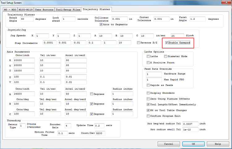
A USB Gamepad such as the one shown below or Logitech’s F310 may also be used to Jog the System. Simply connect the Gamepad and it should become immediately active. The left Joystick controls x and y and the right joystick controls z and a. The same speed parameters in the Tool Setup Screen control both the Jog pushbuttons on the screen and the Gamepad.

The Jog buttons and Gamepad are also active in simulation mode. Note that you must check the box next to “Enable Gamepad” (by default unchecked) in the Tool Setup Screen/Trajectory Planner:
Keyboard Jog

Toggling on Keyboard Jog allows keyboard keys that are normally used for Windows navigation to be used for Jog Functions. These include keys such as arrow, page up/down, +, – etc. Hovering the mouse cursor over a Button will display a tool tip that indicates a keyboard key that may be used instead of the mouse. Mouse clicking into an edit cell that requires the use of arrow keys will automatically de select Keyboard Jogging. The F2 key may be used to toggle Keyboard Jogging.
Feed/Spindle Rate Override

Feed Rate Override (FRO) provides a means to adjust the feedrate while the machine is in operation without having to modify the G Code. The Feed Rate is specified within the G Code using the F command and the FRO is a multiplicative factor that is applied to that value. For example F100 would specify a Feed Rate of 100 inches/minute (or 100 mm/minute if the interpreter is in metric mm mode), with a FRO of 1.5 the actual attempted feed rate would be 150 inches/minute (or 150 mm/minute in mm mode).
Note that this speed will only be used if all the axes involved will remain below the maximum allowed speeds set on the Tool Setup Screen. Additionally, short vectors with sharp corners (greater than the specified break angle) that require stopping may be limited due to acceleration limits. KMotionCNC uses complex Trajectory Planning algorithms to ensure that velocities and accelerations remain below user specified limits. If the FRO or (Specified Feed Rate itself) doesn’t seem to be having the expected result, check if the maximum velocities and accelerations are limiting.
The FRO may be changed either by using the slider or by typing a value and pressing the apply button.
Note that because motions are planned ahead and downloaded to the Motion Controller ahead of time the FRO may take some amount of time to have an effect. The amount of time that the Trajectory Planner looks ahead is specified on the Tool Setup Screen and is normally set at from 1 to 3 seconds. The main limitation to making this value very short is the worst case response time of Microsoft Windows™ and the PC hardware being used.
Hardware Feed Rate Override (within KFLOP) can also be used for a more instant response. However Hardware FRO may result in distorted accelerations. Users can control how FRO is performed using the Feed Rate Override Hardware Range Parameter.
Two numbers at the top of the screen show the last commanded F (Feedrate) setting and the actual instantaneous Feedrate. The actual Feedrate is also plotted as a bar graph as a ratio of actual feed rate to last programmed feed rate.
There is also an independently adjustable Rapid Rate Override. This can be displayed and adjusted by selecting the “rapid” selection. Rapid motions are performed in G Code for G0 type of motion. Rapid Rate Override always uses Hardware Override and has an instantaneous effect.
Feed Rate can be unsynchronized as distance per time for G1,G2, G3 types of motion, or may be Spindle synchronized as distance per revolution for G32 types of Syncronized Threading Motions. When synchronized threading operation is in progress the Feed Rate Icon will be displayed as: ![]() instead of simply as
instead of simply as ![]() for normal operations.
for normal operations.
Similar controls and displays exist for Spindle Control and correspond to the last specified S value in the GCode.
Constant Surface Speed (CSS) is also supported which automatically varies the Spindle Speed as a function of cutting Radius in order to maintain a constant surface speed of the cutting tool across the material. G96/G97 Codes turn on and off this mode. When operating in CSS mode the Spindle Icon will be displayed as: ![]() instead of simply as
instead of simply as ![]() for normal operations.
for normal operations.
3 buttons allow the spindle to be turned on CW, on CCW, to the last specified S setting and SSO. If Spindle Speed feedback is available in the system, the current spindle speed (in RPM) and bar graph will display the ratio of actual Spindle Speed to last programmed Spindle Speed.
Custom Buttons

KMotionCNC allows up to 5 Custom Buttons to be displayed and defined for special operations. Which of these buttons are visible, what they display as a title, and what action they perform are all definable on the Tool Setup Screen.
The actions that the buttons perform are defined by the User in the same manner as the actions that M Codes perform.These may be simple actions such as setting an Output to turn something on or may be a complex operation that involves invoking a program. Normally one or more buttons will be used to initialize and configure the motion controller and/or home the machine.
Other GCode Commands
KMotion’s G Code interpreter was derived from the Open Source EMC G Code Interpreter. Click here for the EMC User Manual (Only the G Code portions of the manual, Chapters 10-14 pertain to KMotion G Code).
Specially coded comments embedded within a GCode program may be used to issue KMotion Console Script commands directly to KMotion.
A comment in the form: (CMD,xxxxxx) will issue the command xxxxxx immediately to KMotion as soon as it is encountered by the Interpreter. Any KMotion command that does not generate a response may be used in this manner.
A comment in the form: (BUF,xxxxxx) will place the command xxxxxx into KMotion’s coordinated motion buffer. Coordinated motion sequences are download to a motion buffer within KMotion before they are executed. This guarantees smooth uninterrupted motion. See here. The BUF command form allows a command to be inserted within the buffer so they are executed at an exact time within the motion sequence. Only the following KMotion Script commands may be used in this manner.
SetBitBuf, ClearBitBuf, SetStateBitBuf WaitBitBuf, WaitNotBitBuf.
Additionally, a comment in the form: (MSG,xxxxxx) will pause GCode Execution and display a pop-up message window displaying the message xxxxxxx.